Bill Coleman Senator Republican ซึ่งยังเป็นสมาชิกของคณะกรรมการกฎกฎระเบียบกล่าวกับสื่อท้องถิ่นว่าโอกาสที่ร่างกฎหมายจะก้าวออกจากคณะกรรมการไปยังวุฒิสภา “ต่ำมาก” จวบจนกระทั่งผู้นำชนเผ่าและที่ทำการผู้ว่าการจะปรึกษาหารือเกี่ยวกับเรื่องในรายละเอียดเพิ่มเติม
จากนั้นเพอร์รี่ก็เริ่มการเดินทางที่ยากลำบากในการเลิกการพนันเขายอมรับว่าเขาเล่นการพนันสองสามครั้งโดยซื้อตั๋วลอตเตอรีและการ์ด FIFA แต่ไม่มีความคิดว่าการกำเริบครั้งนี้เป็นสิ่งที่ไม่ดีตามที่เพอร์รี่กล่าวว่าการเลิกการพนันคือ “เส้นโค้งการเรียนรู้”
ดังต่อไปนี้ มิสซูรี่ นิ้วใกล้กับการทำให้การพนันกีฬาถูกกฎหมายมากขึ้นเรื่อยๆแคนซัสซิตี้ชีฟส์ กำลังไตร่ตรอง ปรับแต่งสนามกีฬาของพวกเขา เพื่อรองรับการเดิมพันกีฬาทีมที่มีชื่อเสียงหลายทีมได้แสดงให้มองเห็นถึงการสนับสนุนอย่างมาก สำหรับการแนะนำ การเดิมพันกีฬาที่ควบคุม ใน Show Me State โดยโต้ถกเถียงว่ามาตรการนี้จะช่วยเสริมการมีส่วนร่วมของแฟนๆและให้กระแสรายได้และภาษีใหม่
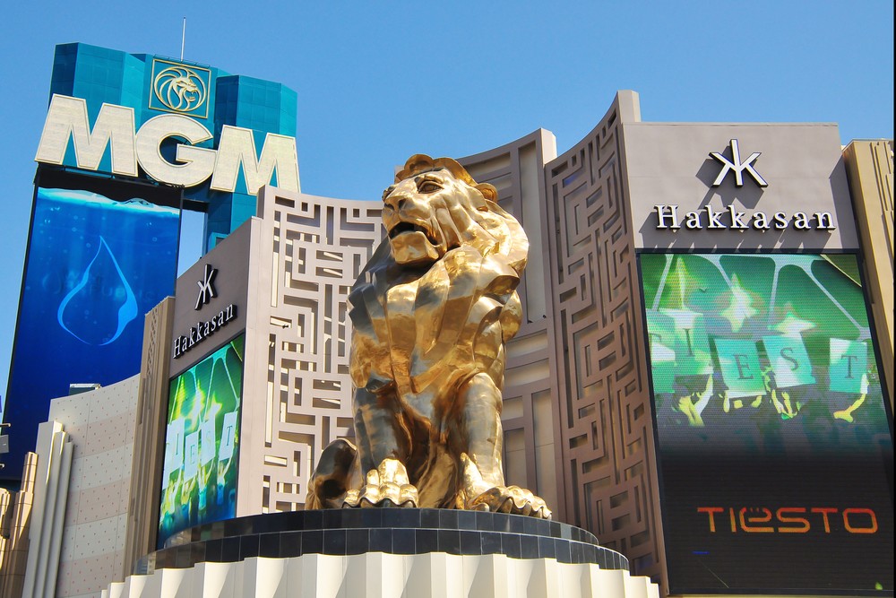
ในระหว่างนี้ IMF ยืนยันว่ากิจกรรมทางเศรษฐกิจของมาเก๊ากำลังประสบกับการฟื้นตัวอย่างมีนัยสำคัญตามรายงาน:
เศรษฐกิจของ SAR ของมาเก๊าขยายตัวขึ้น 80.5 เปอร์เซ็นต์ในปี 2023 ซึ่งผลักดันจากการส่งออกบริการที่เพิ่มขึ้นหลังจากจีนแผ่นดินใหญ่ยกเลิกมาตรการยั้ง COVID-19
คำแถลงของ IMF
IMF เน้นว่าตัวชี้วัดทางเศรษฐกิจที่เอื้ออำนวยได้รับการสนับสนุนจากโมเมนตัมที่ยอดเยี่ยมของภาคการพนันและการกลับมาของกลุ่มการท่องเที่ยวจำนวนมากนอกจากนั้นการส่งออกบริการที่ไม่ใช่เกมยังขยายตัวอย่างมาก
อย่างไรก็ตาม IMF เตือนว่าโมเมนตัมเศรษฐกิจของมาเก๊าประสบกับความผันแปรอย่างมีนัยสำคัญและแสดงสัญญาณของการชะลอตัวในไตรมาสที่ 4 ปี 2023ธุรกิจขนาดเล็กและขนาดกลางที่ไม่ใช่การพนันมีความโชคดีน้อยกว่าภาคการเล่นเกมและการท่องเที่ยว และประสบกับจำนวนการฟื้นตัวที่น่าตื่นเต้นน้อยลง
อย่างไรก็ตาม IMF มองโลกในแง่ดีว่ามาเก๊าจะสามารถกลับสู่ระดับเศรษฐกิจก่อนการระบาดในปี 2025
สำหรับนักแสดงหลักบางคนในมาเก๊า Galaxy Entertainment Group พึ่งจะเผยแพร่ผลการดำเนินงานไตรมาสที่ 4 โดยรายงานตัวชี้วัดที่ดีเนื่องจากการฟื้นของกลุ่มการท่องเที่ยวสำหรับเล่นเกมในทางกลับกัน Melco Resorts มีหุ้นรวมอยู่ในรายชื่อ 10 อันดับแรกของ Morningstar ที่ซื้อขายภายใต้ $10
“ตั้งแต่เริ่มครอบครองตำแหน่งซีอีโอ ฉันมุ่งเน้นไปที่การสร้างกลุ่มเพื่อสร้างมูลค่าที่แข็งแกร่งในอีกไม่กี่ปีข้างหน้าในสหรัฐอเมริกา ความเข้มข้นของการแข่งขันและความต้องการสำหรับขนาดหมายความว่าจำเป็นจะต้องต้องลงทุนจำนวนมากเพื่อให้บรรลุผลผลกำไร” Per Widerström ซีอีโอของ 888 กล่าว“ความร่วมมือของพวกเรากับ Authentic ได้สนับสนุนความต้องการของแบรนด์ SI อย่างสม่ำเสมอทั้งในประสบการณ์ของผู้บริโภคและข้อเสนอผลิตภัณฑ์อย่างตลอดซีรี่ส์ของเดือนที่ทำลายสถิติสำหรับ SI Casino มีมากกว่าให้ความสำคัญกับความแข็งแกร่งของแบรนด์ SIอย่างไรก็ตาม แม้จะประสบความสำเร็จกลุ่มนี้ แต่พวกเราได้สรุปได้ว่าการบรรลุขนาดที่เพียงแค่พอในตลาดสหรัฐอเมริกาเพื่อสร้างผลตอบแทนเชิงบวกภายในกรอบเวลาที่รีบความเร็วไม่น่าเป็นไปได้”
บริษัท ต่าง ๆ ได้ทำข้อตกลงในปี 2021
เพื่อดึงดูดแฟนๆSI เข้าสู่ตลาดการเดิมพันออนไลน์ 888 ดำเนินการในสี่รัฐของสหรัฐอเมริกา รวมทั้งมิชิแกนกับ SI Sportsbook และ SI Casino, SI Sportsbook ในโคโลราโดและเวอร์จิเนียและนิวเจอร์ซีย์กับ 888Casino
ผู้เข้าร่วมการประชุม World Game Protection ในลาสเวกัส ลงคะแนนเสียงในสิ่งที่กลายเป็นรายการ 10 อันดับยอดนิยม นำมาซึ่งเหตุการณ์ในกรงห้าเหตุการณ์รวมถึงเหตุการณ์ที่เกิดขึ้นใน Circa Las Vegas ในเดือนมิถุนายนมันคล้ายกับกรณีอื่นๆของสหรัฐที่ทำให้เกิดการแจ้งเตือนระดับประเทศ
กรณีดังกล่าวเกี่ยวข้องกับกลยุทธ์ทางวิศวกรรมสังคมที่สลับซับซ้อน รวมถึงการใช้สติปัญญาประดิษฐ์ที่เป็นไปได้ ซึ่งสะสมมูลค่า 1.17 ล้านดอลลาร์จาก Circaชายคนหนึ่งอ้างว่าเป็นเจ้าของ Circa ชักนำให้พนักงานกรงแจกจ่ายเงินหลายรายการสำหรับอุปกรณ์ความปลอดภัยจากอัคคีภัยผู้กระทำผิดถูกจับตัวต่อมา
วิลลี อัลลิสัน ซีอีโอและผู้ก่อตั้ง World Game Protection กล่าวว่า
อันดับที่สามในรายการส่งผลให้เกิดการพังทลายในลาสเวกัสในเดือนมกราคม 2023 หลังจากพนักงานของ William Hill ถูกขโมย 280,000 ดอลลาร์ พวกเขาหลอกลวงตู้เดิมพันกีฬาเพื่อให้บัตรกำนัลจ่ายเงินมากขึ้น
“ในทั้งสองกรณี พวกเขาเป็นซินดิเคท ซึ่งเป็นกลุ่มคนจำนวนมากที่ท่วมโต๊ะด้วยชิปปลอม” อัลลิสันกล่าว“โดยปกติแล้วมันจะทำในช่วงเวลาหนึ่งและหยดเข้าไปเพื่อไม่ให้เกิดความสงสัยในกรณีนี้พวกเขาถูกอุทกภัยในช่วงเวลาสองชั่วโมงเพราะมีชิป RFID ฝังอยู่ในนั้นปัญหาคือพวกเขาไม่มีเครื่องอ่าน RFID บนโต๊ะคุณสามารถตรวจชิป RFID ได้ที่กรงเท่านั้นฉันเคยได้ยินว่าปัญหากำลังได้รับการแก้ไข”
Sports Bar & Fanatics Sportsbook ที่ XL Center ของ Hartford ซึ่งเป็นการลงทุนมูลค่า 5 ล้านดอลลาร์ที่เปิดด้วยความคาดหวังสูงในเดือนกันยายนคาดการณ์ว่าอาจขาดทุน 500,000 ดอลลาร์สำหรับปีงบประมาณจบวันที่ 30 มิถุนายน ซึ่งเป็นตัวเลขที่แสดงถึงการเปลี่ยนแปลงจากการคาดการณ์ขาดทุน 750,000 ดอลลาร์ ตามข้อมูลของ Capital Region Development Authority ซึ่งจัดการ XL Center
“พวกเราเปิดตัวมันกับ Rush Street เพราะว่าพร้อมใช้งาน มันเป็นโครงการขนาดใหญ่มาก” Andrew Walter ผู้อำนวยการฝ่ายกฎหมายและธุรกิจของแผนกเดิมพันกีฬาของ The Connecticut Lottery Corp อธิบายกับ Hartford Courant “Rush Street กำลังออกไปสองสามเดือนต่อมา ด้วยเหตุดังกล่าว (Sportbook) จึงไม่ได้รับความบันเทิงหรือความสนใจจากด้านการตลาดที่อาจจะได้รับ”
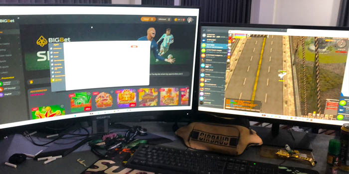
อเลฮานโดร เทงโกประธานเจ้าหน้าที่บริหารและประธานเจ้าหน้าที่บริหารของ PAGCOR แสดงความความเห็นเกี่ยวกับเรื่องนี้ โดยกล่าวว่าเจ้าหน้าที่ทำการค้นหาถังและจับผู้ต้องสงสัยด้วยมือผู้ต้องสงสัยขณะดำเนินการแพลตฟอร์มการพนันที่ผิดกฎหมาย เดิมพันใหญ่ (ทีบีบ888. คอม)จากข้อมูลของ Tengco The Big Bet นำเสนอผลิตภัณฑ์การพนันที่ผิดกฎหมายเป็นต้นว่าเครื่องสล็อตผลิตภัณฑ์คาสิโนสดและการเดิมพันอีสปอร์ตเป็นต้น
Villanueva กล่าวเพิ่มเติมเกี่ยวกับเรื่องนี้โดยกล่าวว่าการดำเนินการนี้เป็นส่วนหนึ่งของความพยายามแบบรวมของหน่วยงานฟิลิปปินส์ในการขัดขวางกิจกรรมการพนันที่ผิดกฎหมายเขากล่าวว่าหน่วยงานกำกับดูแลสัญญาว่าจะทำงานร่วมกับหน่วยงานบังคับใช้กฎหมาย ได้แก่ PNP และหน่วยงานประสานงานข่าวสารกรองแห่งชาติเพื่อหยุดปฏิบัติการดังกล่าว
Raul Villanueva รองประธานอาวุโสฝ่ายความปลอดภัยและการตรวจสอบคลัสเตอร์ PAGCOR
Villanueva ขอให้ประชาชนหยุดโต้ตอบและใช้จ่ายเงินบนแพลตฟอร์มที่ผิดกฎหมายดังกล่าวและกล่าวว่าน่าสลดใจที่เหยื่อของเว็บไซต์ที่ผิดกฎหมายส่วนมากเป็นผู้เล่นชาวฟิลิปปินส์เขากล่าวว่าต้องต้องมีการตรวจสอบและรายงานอย่างเป็นประจำเพื่อปกป้องผู้เดิมพันและตรวจสอบให้แน่ใจว่ารายได้จากการเล่นเกมที่มีการควบคุมจะถูกส่งกลับไปยังรัฐบาล
เกมใหม่เรียกว่า Match 5 และจะช่วยให้ Sky Bet แยกความแตกต่างของข้อเสนอออนไลน์จากคู่แข่งการรวมองค์ประกอบของ iGaming และการเดิมพันกีฬา เกมใหม่นี้ช่วยให้แฟนๆสามารถเลิศชมแอป Sky Bet ทุกวันเพื่อรวบรวมทีมพรีเมียร์ลีกที่แตกไม่เหมือนกัน
ในการอัปเดตบน LinkedIn Incentive Games ทำให้เห็นว่าผลิตภัณฑ์ใหม่ได้เพลิดเพลินกับ “การนำมาใช้ที่ยอดเยี่ยม” ในอาทิตย์แรกผู้ให้บริการมีความตื่นเต้นที่ได้เห็นว่าความร่วมมือกับ Sky Bet นี้จะพัฒนาอย่างไร
การแข่งขัน 5 จะเปลี่ยนเกม
John Gordon ผู้ร่วมก่อตั้งและประธานเจ้าหน้าที่บริหารของ Incentive Games กล่าวว่าทีมของเขาตื่นเต้นมากกับเกมนี้เขาอธิบายว่าเป็น “ตัวอย่างคลาสสิกของข้อมูลเชิงลึกที่เรียบง่าย เข้าถึงได้ง่าย และการมีส่วนร่วม” โดยกล่าวว่ามันจะเป็นวิธีสำหรับผู้ที่ชื่นชอบฟุตบอลที่จะยกระดับประสบการณ์ของพวกเขาไปอีก
เมื่อรวมกับมาตราส่วนของ Sky Bet นี่คือการเปลี่ยนแปลงเกมที่แท้จริง
จอห์น กอร์ดอน ผู้ร่วมก่อตั้งและซีอีโอของ Incentive Games
ในระหว่างนี้ Dan Colton กรรมการผู้จัดการของ Sky Bet กล่าวว่า Match 5 เป็น “จุดสุดยอดของการทำงานหนักหลายเดือน”เขายกย่องทีมของ Incentive Games สำหรับการทำงานที่น่าทึ่งในเกมและกล่าวว่า Sky Bet ไม่สามารถรอได้ว่าลูกค้าโต้ตอบกับมันอย่างไร
เมื่อเดือนที่แล้ว Sky Bet ได้เปลี่ยนแปลงโปรโมชั่นการรับประกันอัตราต่อรองที่ดีที่สุด (BOG) ซึ่งจำกัดการเข้าถึงสมาชิกโปรแกรมความภักดีของ Sky Bet Club ที่ใช้งานอยู่แม้จะมีการเปลี่ยนแปลงกลุ่มนี้ แต่ Sky Bet ยังคงเชื่อมั่นในความสำเร็จของการเสนอขาย
Checkd Dev ซึ่งเป็นส่วนหนึ่งของ Checkd Group วันอังคารได้ประกาศเปิดตัวแอป Boxing News ร่วมกับ iD Sports Mediaแอพนี้จะนำเสนอเกมคาดการณ์ที่เล่นฟรี การ์ดคะแนนแบบโต้ตอบ และความพร้อมในการวางเดิมพันกับพันธมิตรปฏิบัติการ Bet365
“มีช่องว่างที่ชัดเจนสำหรับผลิตภัณฑ์เช่นนี้ภายในมวย และเป็นเรื่องที่ยอดเยี่ยมสำหรับเราที่สามารถเป็นพันธมิตรกับ Boxing News และมีความน่าวางใจและประเพณีอันยาวนานเช่นนี้” Adam Patton กรรมการผู้จัดการ Checkd Dev กล่าวในแถลงการณ์“เราเชื่อว่าผลิตภัณฑ์ของเราจะตอบสนองอย่างมากกับผู้ที่ชื่นชอบมวยทั่วโลกการผสมผสานความรู้ของ Checkd Dev เกี่ยวกับเทคโนโลยีการเดิมพันกีฬาและความรู้และความเชี่ยวชาญของทีม iD Sports Media เป็นสิ่งที่ชนะได้”
ระหว่าง Checkd Dev และ iD Sports Media ผ่านข้อตกลงเชิงพาณิชย์หลายปีใหม่
“ในการค้นหาพันธมิตรเพื่อส่งมอบแอป Boxing News เราพยายามเจาะจงนักพัฒนาที่สามารถสร้างผลิตภัณฑ์ที่น่าสนใจด้วยเส้นทางผู้ใช้ที่เรียบง่ายและใช้งานง่าย” Rob Tebbutt ผู้อำนวยการฝ่ายจัดการ iD Sports Media กล่าว“Checkd Dev ได้หาแอปที่ประสบความสำเร็จในการมีส่วนร่วมกับผู้ชมที่เรารู้จักกันดีด้วยการที่ปี 2024 กลายเป็นปีที่ยิ่งใหญ่สำหรับกีฬา พวกเราจึงมั่นใจว่าแอป Boxing News จะสร้างตัวเองให้เป็นสิ่งที่ต้องมีสำหรับแฟนมวยและกลายเป็นหัวใจสำคัญของการต่อสู้ใกล้สำหรับแฟนมวยฮาร์ดคอร์และสบายๆเหมือนกัน”
Sarah Fox รองผู้อำนวยการกรมดิจิทัล วัฒนธรรม สื่อ และกีฬา (DCMS) ของสหราชอาณาจักรกล่าวว่ารัฐบาลมีเป้าหมายที่จะมีการปรับปรุงเอกสารไวท์เปเปอร์การพนันจำนวนมากดำเนินการภายในฤดูร้อน
เมื่อบอกในประชุมเปิดการบรรยายสรุปกฎระเบียบโลกที่ ICE Vox เมื่อเช้านี้ Fox กล่าวว่าแผนกหวังว่าจะเผยแพร่ผลการขอความเห็นอย่างต่อเนื่องภายในไม่กี่สัปดาห์และต้องการให้มีการปฏิรูปเอกสารส่วนใหญ่ภายในฤดูร้อนนี้
จอห์น โอเรลลี่ ประธานเจ้าหน้าที่บริหารของ The Rank Group
ปีที่แล้ว เอกสารไวท์เปเปอร์ทบทวนกฎหมายการพนัน ได้รับการเผยแพร่โดยสรุปข้อเสนอแนะหลายประการที่คาดว่าจะยกเลิกอุตสาหกรรมการพนันทั่วประเทศอย่างสมบูรณ์ในบรรดาการเปลี่ยนแปลงที่เสนอ ได้แก่ การดำเนินการจำกัดสำหรับสล็อตออนไลน์การเปลี่ยนแปลงอัตราส่วนของอุปกรณ์การพนัน B และ C ตลอดจนการดำเนินการตรวจสอบราคาไม่แพงรวมทั้งการปรับแต่งอื่นๆ
Global Gaming Women วันพฤหัสบดีแนะนำ Lauren Bates ผู้บริหารอาวุโสในอุตสาหกรรมเกมในฐานะประธานคณะกรรมการคนใหม่ของบริษัทอุตสาหกรรมเกมไม่แสวงหากำไรยังได้เปิดตัว Light & Wonder EVP & Group CEO Gaming Siobhan Lane เป็น 1st รองประธานและแบรนดี เอลลิส ผู้จัดการฝ่ายการตลาด Caesars Entertainment AS 2เอนด์ รองประธานาหัวหน้า
Global Gaming Women ยังประกาศนัดหมายตั้งแต่นี้ต่อไป:
ผู้เก็บเงิน: ซาแมนธา ฮัฟฟ์-ชลูเตอร์ ผู้จัดการอาวุโส กลุ่มบริการประกันภัยที่ RubinBrown LLP
เลขานุการ: Kate White รองประธานฝ่ายข่าวสารกรองและการจัดการโปรแกรมไอทีที่ PENN ENTERTAINMENT
ที่หารือทั่วๆไป: Kelci Binau ทนายความที่ McDonald Carano
Plaza Hotel & Casino ในเมืองลาสเวกัสได้จ้าง Christiaan van Buuren เป็นผู้อำนวยการฝ่ายเกมบนโต๊ะและส่งเสริมผู้บริหารอาหารและเครื่องดื่มสองคน
ไรอัน โรว์แลนด์ ได้รับการเลื่อนขั้นเป็นรองประธานโครงการอาหารและเครื่องดื่มของอสังหาริมทรัพย์Courtney Allen จะเข้าดำรงตำแหน่งผู้อำนวยการฝ่ายอาหารและเครื่องดื่ม
บัณฑิตจากมหาวิทยาลัยโยฮันเนสเบิร์ก
ภูมิหลังของ van Buuren ในด้านการดำเนินงานของคาสิโนและโรงแรมมีตั้งแต่การวางแผนก่อนเปิดและออกแบบกับ Gold Reef Casino Resorts ในแอฟริกาใต้พื้นบ้านของเขาไปจนถึงการเดินทางไปทั้งโลกในการจัดการการดำเนินงานคาสิโนบนเรือล่องเรือล่องเรือหรูหกดาวกับ Regent Seven Seas Cruises
ยิ่งไปกว่านี้เขายังเป็นหัวหน้าแผนกเกมคาสิโนของ Kangwon Land, Inc. ซึ่งเป็นเซอร์วิสอพาร์ทเม้นท์คาสิโนรวมขนาดใหญ่ในเกาหลี ซึ่งเขาได้สร้างสรรค์การดำเนินงานคาสิโนและการเฝ้าระวังของพวกเขาเขามาที่ลาสเวกัสเพื่อเป็นส่วนหนึ่งของทีมเปิด SLS จากนั้นย้ายไปเป็นผู้นำการเปลี่ยนแบรนด์คาสิโนที่ The STRAT
โรว์แลนด์ เข้าร่วมทีมอาหารและเครื่องดื่มของพลาซ่าในปี 2019 ในฐานะผู้อำนวยการก่อนที่พลาซ่า โรว์แลนด์เป็นผู้อำนวยการร้านอาหารสำหรับการเปลี่ยนแปลง Monte Carlo Resort & Casino เป็น Park MGM และอาชีพของเขารวมถึงตำแหน่งผู้บริหารในร้านอาหารที่มีชื่อเสียงอย่างเช่น Spago Las Vegas, Michael Mina ที่ Bellagio, StripSteak ที่ Mandalay Bay และ Jean-Georges Prime Steakhouse
“การมีทีมผู้บริหารที่มีคุณสมบัติเหมาะสมและทุ่มเททำให้พลาซ่าสามารถมอบประสบการณ์ที่ไม่มีใครเทียบได้แก่แขกในใจกลางเมืองลาสเวกัส” Jonathan Jossel CEO ของ Plaza Hotel & Casino กล่าว“ฉันตื่นเต้นที่จะต้อนรับ Christiaan และมั่นใจว่าภูมิหลังที่หลากหลายของเขาจะยกระดับการดำเนินงานของคาสิโนของเราถัดไปและฉันขอแสดงความยินดีกับ Ryan และ Courtney ในความสำเร็จในการยกระดับโปรแกรมอาหารและเครื่องดื่มของพวกเราตั้งแต่การมอบประสบการณ์สเต็กเฮาส์ที่แท้จริงที่ Oscar ไปจนถึงการพัฒนาในโปรแกรมค็อกเทลงานฝีมือที่ไม่เหมือนใครที่ Carousel Bar แห่งใหม่ของพวกเรา วิสัยทัศน์ที่สร้างสรรค์และการดำเนินการอย่างราบรื่นของพวกเขาจะเป็นสิ่งสำคัญเนื่องจากว่าพลาซ่ายังคงสร้างข้อเสนอใหม่ให้กับแขกของเราอย่างตลอด”
Christina Renna ประธานและซีอีโอหอการค้าทางตอนใต้ของนิวเจอร์ซีย์กล่าวว่าในขณะที่การสูบบุหรี่เป็นอันตรายอย่างไม่ต้องสงสัยด้วยเหตุนั้นอาจเป็นการเลิกว่าจ้างที่เธอและผู้บริหารจากอุตสาหกรรมคาสิโนเตือนอาจเกิดขึ้นได้ถ้าห้ามสูบบุหรี่
Donna DeCaprio ประธานของ Local 54 ของสหภาพ Unite Here
ในการอภิปรายออนไลน์กับเซนเตอร์ Joseph Vitale ประธานประธานประชาธิปไตยของคณะกรรมการ เธอกล่าวว่าคุณเตือนว่าคาสิโนแอตแลนติกซิตี้ได้มากถึงสามแห่งอาจถูกบังคับให้ปิดถ้าเกิดมีการห้ามสูบบุหรี่ในขณะที่คาสิโนในเพนซิลเวเนียที่อยู่ใกล้เคียงยังคงนำเสนอ
Cynthia Hallett ประธานและซีอีโอของ Americans for Nonsmokers’ Rights กล่าวว่าการสำรวจแสดงให้มีความเห็นว่าผู้คนจำนวนมากกล่าวว่าพวกเขาจะเยี่ยมชมคาสิโนแอตแลนติกซิตี้หากห้ามสูบบุหรี่
ร่างกฎหมายที่ดำเนินการในวันจันทร์ตอนนี้จะไปที่วุฒิสภาเต็มรัฐเพื่อลงคะแนนเสียงร่างกฎหมายที่เหมือนกันจะต้องได้รับการอนุมัติจากคณะกรรมการสภา และโหวตโดยห้องเต็มก่อนที่จะสามารถไปที่โต๊ะของรัฐมนตรีประชาธิปไตย Phil Murphy ซึ่งกล่าวว่าเขาจะลงนามในกฎหมายห้ามสูบบุหรี่